![]() The Cable tool is designed
to show interconnections between symbols in the Block Schematic and Pictorial
Schematic environments.
The Cable tool is designed
to show interconnections between symbols in the Block Schematic and Pictorial
Schematic environments.
ALWAYS use Cables to show interconnections and not Lines or any other object. Cables have special features, attributes and behaviors that will improve your productivity.
There are several ways to draw a Cable:
Click and drag; this creates a 3 segment Cable.
Click once to start, click once for each node and doubleclick, or press Escape (Esc) on your keyboard to finish.
When you have created one or more cable segments, click and drag to create 2 perpendicular segments.
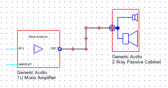
Cables are designed to start and end at connection points:
|
Figure 1 |
Cables should always be drawn so that their start and endpoints sit on the point where a symbol's I/O stubs (in Cyan) meet the red outline of the symbol: this is critical for rubberbanding to function.
When you use the Cable tool a round blue highlight will appear showing that you are at a valid connection point. Your Cable will auto-terminate at a valid connection and connected Cables show a square blue handle. Figure 1 shows a correctly drawn Cable with a connection handle at the start point (left) and a connection highlight at the endpoint.
The Cable tool should normally be used with the Snap to Grid modifier on because symbol I/Os are designed and drawn to appear on gridpoints.
When a Cable is connected to a symbol, if you move the symbol the Cable will redraw itself to maintain its connection. This is called Rubberbanding and it's a feature of Cables that saves a lot of time as designs evolve; you don't have to waste time re-drawing cables manually whenever you move symbols.
Using the Selection cursor, rightclick on a Cable to add or delete a node. By adding nodes you can effectively add segments to a Cable. To delete a node you must rightclick quite close to the node, within 10 pixels.
Labels are special attributes that can be used to identify the Cable. When you set Cable Label values they are displayed on the drawing.
To set Cable Label values:
The Cable Label tool has many advantages over setting Label values manually: it allows you to:
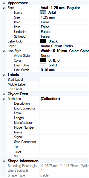
The appearance and formatting of Labels is set using the Font and Label Color properties shown in the Properties Grid.
The values of Cable Labels are output as part of the Cable Schedule.
Cables support a unique set of Attributes, e.g. "Start Connector", "End Connector", "Length" etc., which deal with the specific nature of Cables and the function they perform and these attribute values are output as part of the Cable Schedule. See "Properties Grid for Cable object" below for details of default Attributes in Cables.
You can modify the default Cable attributes using Tools | Personalization | Settings.
 Font
group: displays a summary of all the current Font
values applied to Cable Labels. Read-only:
use the members of the Font group to set values.
Font
group: displays a summary of all the current Font
values applied to Cable Labels. Read-only:
use the members of the Font group to set values.
Label Color: shows the current Cable Label color. Click on the value field to choose a new Color for the Labels.
Layer: shows the layer on which the object exists. Click on the value field to move the object to a new layer.
Line Style group: displays a summary of all the current Line Style values. Read-only.
Labels: displays current Label values. Use these fields to set the values of Start, Middle and End labels manually.
Attributes: displays and allows you to set Attribute values for the Cable.
The Shape Information collection is read-only and displays information about the currently selected object(s).
Cable defaults are set in the Document Properties Grid | Drawing Defaults collection - use this to define default values for Arrow Style, Color, Dash Style and Line Width.
To quickly assign pre-defined styles, layers, labels and attribute values to your Cables use Cable Presets.
The movie below shows how to use the Cable Tool to show system interconnections, how to draw multi-segment cables quickly and easily and includes tips and tricks, shortcuts and accelerators.
Other Commands: |
Menu: |
Drawing, Cable |
See Also: |
||