Rack Layout
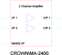
Block Schematic
Pictorial Schematic


Symbol Scale: 1:1
Symbol Scale: None
Symbol Scale: 1:9.693
Symbols are graphical representations of products that can be inserted into drawings using the Product Browser or the Available Symbols Palette.
Symbols conform to a strict data specification that defines their size, shape, colors used, and the layers on which objects are placed. For full details see the Help topic for Modules: the data specification for symbols is shown in each Module topic.
Depending on the drawing type (Module) in which you're working, the same amplifier by Crown is shown in these ways:
Rack Layout |
Block Schematic |
Pictorial Schematic |
|
|
|
Symbol Scale: 1:1 |
Symbol Scale: None |
Symbol Scale: 1:9.693 |
 It's important
to note that drawing templates are designed to be used with the Snap
to Grid modifier active. The symbols are all drawn with precisely
defined insertion points so that when you drag the symbol into the drawing
it will sit neatly on the grid and align with the other symbols in the
drawing. For example, the insertion point for rack mounted products in
Rack Layout drawings is exactly on the bottom left hand corner of the
unit, while for all products in the Panel Layout environment it is dead
center.
Insertion Points by Drawing Type |
|||
Block Schematic |
Panel Layout |
Pictorial Schematic |
Rack Layout |
|
|
|
|
These diagrams give a general guideline as to how symbols are inserted into each of the environments: the target represents the point which sits exactly on the tip of your cursor as you drag the symbol into your drawing. It should be noted that there are exceptions to these rules, for example when inserting Modular Symbols, and more detailed explanation is given in the sections that deal with the specifics of each drawing Module.
You can create your own symbols within User Defined Products.