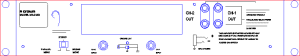
Rear View, Before Insertion
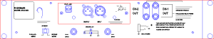
Rear View, After Insertion
There are certain products that must be inserted onto or into other products. As a general rule these products cannot be positioned directly on to the grid, rather they will be put into or onto a sub-frame or assembly which does go on the grid. Examples of such modular equipment would be optional input/output cards that fit into 19" rack-mounted products (like input cards for amplifiers) or compression drivers that bolt onto horns.
To cater for this eventuality, the sub-frame will contain module targets on a specific layer. You can display these targets by checking "Module Targets" in the Layers Dialog. The target will look like a vertical bow-tie and the insertion point of the module that fits into the sub-frame should be positioned on its thinnest point. The only way to accurately position modules is therefore by use of the Snap to Path modifier. Note that, for environments with a rear view, front insertion targets are green, rear insertion targets are red.
In this Rack Layout example a Crown MA2400 amplifier is the sub-frame that houses a Crown PIP-AMC card. With the module targets displayed and the Snap to Path modifier active it is easy to position the module correctly. The result is shown below.
|
|
Rear View, Before Insertion |
Rear View, After Insertion |
It is recommended that modular insertion should be carried out in Low Detail view to reduce the number of visible objects that the module could snap to. It is also strongly recommended that all parts insertion, modular or otherwise, be carried out in the Front views.
See Also: |