Layer Name |
Purpose/Convention |
Sample |
Work
Layer |
[User] General purpose working
layer. (No objects appear on this layer in symbols) |
|
Outline |
Not
used. Provided for compatibility with Rack Layout environment. |
|
Front
Low Detail |
Not
used. Provided for compatibility with the Rack Layout environment. |
|
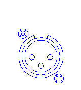
Front
High Detail |
Accurate
graphical representation of the front of products. |
|
Rear
Low Detail |
Not
used. Provided for compatibility with the Rack Layout environment. |
|
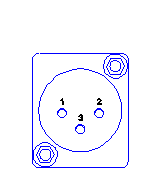
Rear
High Detail |
Accurate
graphical representation of the rear of products including pin
numbers where appropriate. |
|
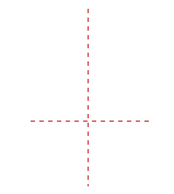
Guide
Lines |
Horizontal
and vertical centre lines to allow for accurate positioning. |
|
Visual
Notes |
[User] For general comments
regarding layout or any other general construction directions. |
|
Punching |
Cutouts
required to mount the product. |
|
Punching
Dimensions |
[User] For the addition of
measurements giving details of the position of cutouts specifically. |
|
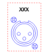
Engraving |
A
text field is provided ("XXX") which can be edited to
show engraving or labelling |

|
Engraving
Dimensions |
[User] For the addition of
measurements giving details of the position of engraving specifically. |
|
Clearances |
The
recommended distance required to allow for fixing or manipulation
of connectors, their associated cables and any other items (e.g.
levers and latches) |
|
Assembly
Notes |
[User] For general instructions
to those assembling the panel. |
|
Wiring
Notes |
[User] For general instructions
to those wiring the panel. |
|
Insert
Outline |
Not
used. Provided for compatibility with legacy applications. |
|
System
References |
[User] Any information required
by the user to identify components within the system. |
|
Module
Targets |
Insertion
targets for modular equipment which needs to be precisely located
within a sub-frame. |
|
Title
& Borders |
[User] Drawing border and any
information used to reference the drawing (company details, project,
drawing number etc.). |
|