Layer
Name |
Purpose/Convention |
Sample |
Work Layer |
[User] General purpose working
layer. (No objects appear on this layer in symbols) |
|
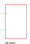
Outline |
The
outline, description and model number of the product as well as
the principle input/output stubs.. |
|
Audio Circuit Paths |
[User] Connections and notes
pertaining to audio signal paths (e.g. Mic level, Line level and
Speaker level). |
|
Video Circuit Paths |
[User] Connections and notes
pertaining to video signal paths (e.g. S-VHS, RGB/Synch etc.). |
|
Lighting Circuit Paths |
[User] Connections and notes
pertaining to lighting signal paths (e.g. DMX etc.). |
|
Control Circuit Paths |
[User] Connections and notes
pertaining to control signal paths (e.g. RS232, control voltage
etc.). |
|
Power Circuit Paths |
[User] Connections and notes
pertaining to power signal paths (e.g. mains, DC etc.). |
|
User Circuit Path 1 |
[User] Connections and notes
pertaining to user-specified signal paths. |
|
User Circuit Path 2 |
[User] Connections and notes
pertaining to user-specified signal paths. |
|
Mechanical Interconn. |
[User] Mechanical relationships
not usually shown in pictorial schematic format (e.g. rack housings,
physical locations etc.). |
|
System References |
[User] Any information required
by the user to identify components within the system. |
|
Module Targets |
Insertion
targets for modular equipment which needs to be precisely located
within a sub-frame. |
|
Title & Borders |
[User] Drawing border and any
information used to reference the drawing (draughtsman, company
details, project, drawing number etc.). |
|
3D Representations |
Isometric
3D projections of loudspeaker enclosures. Note that these are
not perspective projections, therefore the eye may perceive rectangular
enclosures as "looking odd". Trapezoidal enclosures
will look correct since they appear to be in perspective. |

|
Rear High Detail |
Accurate
graphical representation of the rear of products (excluding outline).
This layer is the only place you will find details of the rear
view of products which are not rackmounted. |
|
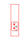
Front High Detail |
Accurate
graphical representation of the front of products (excluding outline). |

|

