 .
.|
How Do I ... ? |
Write my Own Driver |
|
|
This topic introduces the procedures and techniques you can use to develop your own device drivers.
There is a multimedia walk-through of these techniques in the online
Technical
Resources.
Read this section and still have a problem you just can't solve or get working? Someone in the Support Forums or a Certified Programmer may be able to help.
Most manufacturers of devices that can be controlled via serial or Ethernet make their control protocols freely available. Check with your device's manufacturer as to the availability of their protocol documentation; you may find that it is available for download from their website.
Ensure that you obtain the correct protocol documentation for the particular model of device you have.
Some protocols are commercially sensitive and proprietary, and such
technical information may not be available at all, or only available under
license. Examples
of proprietary and licensed protocols are EtherSound and PathPort.
These protocols are fully supported within Stardraw Control, as they have been acquired under license or other agreement. Whilst you cannot examine the actual implementation of these, the drivers supplied in Stardraw Control can usually be extended and built upon like any other driver.
Note
If your device uses a proprietary protocol not currently supported by Stardraw Control, you could request that it be considered. Please refer to the Support section for further assistance.
There is some basic information that you require from the protocol documentation:
Transport: the communication method used, e.g. serial, TCP/IP, UDP, SNMP, HTTP,
Port Configuration: port settings, e.g. baud rate, IP address, TCP or UDP ports,
Command Format: whether the command data is transmitted as text or binary, encoding schemes, line terminators, etc.
Command Structure: how commands are put together, e.g. start characters, lengths, delimiters, parameters, end characters, checksums, etc.
The first two points, transport and port configuration, will usually be straightforward to set up in your new driver, as Stardraw Control includes built-in support for managing serial, Ethernet, SNMP, MIDI and infrared ports, and enables you to easily build your driver up from these.
The last two points, command format and structure, will be addressed as part of writing the driver protocol itself.
A Stardraw Control driver consists of one or more Ports, that are associated with a Manufacturer, a Device Model and a Description.
Ports represent connection points on your device, and include a Port Type (e.g. RS232 input, Ethernet input, etc.) and a script that contains the protocol for that device's port. Refer to Defining your System for an introduction on ports and protocols.
Ports are actually Microsoft.Net classes, which are simply objects that encapsulate all the functionality required to communicate with COM, Ethernet, TCP, UDP, SNMP and MIDI ports, etc. Classes are a standard way of programming using Microsoft.Net technology. Stardraw Control provides base classes for each type of input or output port.
The scripts within a driver are again standard Microsoft
C# programs that use the base classes provided by Stardraw
Control. A
script adds its own unique functionality that provides all of the protocol
functions and features supported by the driver. You
can find many resources on C# programming in print and online.
The complexity of the script is ultimately determined by the complexity of the protocol itself. Many serial and Ethernet protocols are unidirectional, that is, communication occurs in one direction only: from the controller to the device.
Some protocols are bidirectional, where the device will respond to the controller with success or failure confirmation, status changes, alerts or errors and sometimes heartbeat data which enables the control application to monitor the device and vice versa. If the communication link is broken, or some other failure occurs, either end of the communication link can detect the absence of heartbeat messages, and react accordingly.
Generally unidirectional drivers are much simpler to write than bidirectional ones. Processing incoming data is often made difficult by the way the protocol itself is structured, and can require processing many iterations of input data before a command is recognized. Writing bidirectional drivers is usually an advanced programming task.
Tip
Devices that use bidirectional protocols do not necessarily require your control application to receive and process incoming data from the device. In this case you can write your driver as if the protocol were unidirectional, making the implementation much simpler. Full support for the bidirectional features can always be added at a later stage.
The device that will be used in the following example is a Digital Projection Highlite
12KDsx projector. The
protocol document was an easily obtained PDF file downloaded from the
manufacturer's website.
From the protocol document we can now address the four main points:
Transport: the projector supports RS232, Ethernet and USB: our example driver will use RS232.
Port Configuration: the RS323 settings are 38,400 bits per second, 8 data bits, no parity, 1 stop bit, full duplex.
Command Format: command data is transmitted as binary.
Command Structure: commands are 5 or more bytes The smallest unit of data that can be stored or transmitted in a computer system. A byte is eight bits long, and can hold an integer value of 0 to 255 or 0x00 to 0xFF. long, and the last byte is a checksum of all the preceding bytes.
This protocol is also bidirectional: it responds with a success or failure message for each command sent by the control program, and also supports querying the device for numerous parameter and status values. For the purpose of this example, however, we will treat the protocol as if it were unidirectional.
Here is an extract of the command protocol for the two functions that we will implement (shown in hexadecimal A base-16 number system, also called hex: decimal values 0 through 15 are represented by the digits 0 through 9 and the alphabet digits A through F. notation):
|
Function |
Command Data |
|
Power On |
0x02 0x00 0x00 0x00 0x00 0x02 |
|
Power Off |
0x02 0x01 0x00 0x00 0x00 0x03 |
The Power On and Power Off functions are fixed-length commands of six hex bytes each, including the last checksum byte. These commands can be very easily transmitted to the projector via the serial port.
To create a new device driver,
In the Topology View
click the Add New Product button,
or select Add New Product from
the Tools menu, or press F8.
The Add New Product
dialog will open:
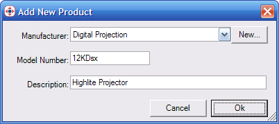
The Add New Product dialog
Select the Manufacturer Name "Digital Projection" from the list: if it is not present, click New to define a new manufacturer.
Enter the Model
Number of "12KDsx", and a Description
of "Highlite Projector". Click
OK.
The Product Properties
dialog will open:
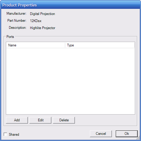
The Product Properties dialog
Click Add to add a new Port: the Port Properties dialog will open:
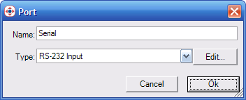
The Port Properties dialog
Enter "Serial" as the Name, and select "RS232 Input" as the port Type.
Click Edit: the Script Editor will open and display the default script for the selected port type.
The next step is to modify the default script to add the protocol functions we wish to the driver to support.
In the default script, the driver's class derives from the SerialInPortInstance base class. This base class provides all the functionality required to communicate with your computer's COM ports.
public class MyClass : SerialInPortInstance
The default script contains some basic initialization code, some general comments and commented-out demo code. To add the protocol functions to the driver, we can create additional methods, or functions, to the class, that are accessible from the Actions dialog so that we can control the device.
Tip
The comment lines, displayed in green, are for documentation purposes and do not affect the driver's operation. You can delete these lines if you wish to make the script tidier to read and edit.
For the Power On command, we can create a simple function that sends the corresponding six hex bytes to the serial port. Add the following code fragment to the MyClass class:
[Controllable]
public void PowerOn()
{
// send the Power On command data to the serial port
Write( new byte[] { 0x02, 0x00, 0x00, 0x00, 0x00, 0x02 } );
}
This creates a new method called PowerOn that:
sends a group of six bytes to the serial port by calling the SerialInPortInstance base class's Write method, which performs the task of sending the data to the serial port,
there is no need to open the COM port or worry about the baud rate or other settings: the base class takes care of all this for us,
the [Controllable] attribute makes the function accessible from the Actions dialog, so that we can use later it to control the driver.
Click Compile: Stardraw Control will verify and compile your code changes. If no error messages appear, click OK to close the Script Editor. Click OK to close the Port Properties dialog.
Before closing the Product Properties dialog, the Shared option can be cleared if you do not wish to share your new device driver with other Stardraw Control users; otherwise leave this option set.
Notes
Marking a driver as Shared will upload a copy to Stardraw.com: we will check your code and validate the driver, and then publish and support it so that all Stardraw Control users can use the driver.
If you have trouble compiling your changes, the script (some comments omitted) should look like this:
using System;
using Stardraw;
using Stardraw.Project;
using Stardraw.Control;
using Stardraw.Serial;
[Serializable]
public class MyClass : SerialInPortInstance
{
public MyClass( ProductInstance productInstance, Port port ) : base( productInstance, port )
{
}
[Controllable]
public void PowerOn()
{
// write an array of bytes to the serial port
Write( new byte[] { 0x02, 0x00, 0x00, 0x00, 0x00, 0x02 } );
}
}
Finally, click OK to accept the changes to the new driver: it will appear in the My Libraries list.
In the above example, the script uses the Controllable Property pattern. Adding the [Controllable] attribute makes the method accessible from the Actions dialog.
You can now use the new device driver and test the new command in the same way as any other device.
In the Topology View, locate the 12KDsx Highlite Projector from the Digital Projection category in the My Libraries list.
Click and drag the device to add it to your topology.
Connect the Serial input port of the projector device to the corresponding COM port of your Computer device.
Select the Computer device and in the Properties Grid, set the BaudRate to 38400 for the COM port you just connected.
In the Forms View, from the Controls tab of the Toolbox, click and drag a Switch control onto the form.
Double-click the switch
control to display the Actions Editor.
The selected event is switch1.Click:
this is the event that we wish to capture to power up the projector.
Add the following Action
to call the PowerOn method of
the projector:
Devices –
12KDsx (1) –
Serial –
PowerOn
Add a Condition to the
Action:
Controls –
When Form1 –
switch1 –
Checked –
is equal to –
Variables –
True
Click Ok to close the Actions dialog.
Run the project: when you switch the control on, in the Debug Window, you will see the debug output from the form: the switch control's Click event is followed by the condition check, then the PowerOn method is executed, which writes the data bytes out to the serial port. You can use the debug output to verify that the form and driver are working, even without a projector device connected to your system.
01/01/2007 08:36:58 Info switch1, Click
01/01/2007 08:36:58 Debug Condition switch1.Checked Equal "True", Yes
01/01/2007 08:36:58 Info Action 12KDsx (1).Serial.PowerOn, Executed
01/01/2007 08:36:58 Debug 12KDsx (1)Serial, Write ASCII ..... Hex 02 00 00 00 02 Decimal 2 0 0 0 2
01/01/2007 08:36:58 Debug Computer (1).COM1, Write ASCII ..... Hex 02 00 00 00 02 Decimal 2 0 0 0 2
To add the Power Off command, we can create another function to the existing driver.
Note
Modifying an existing device in the Topology View will alter only that copy in the current project. Alternatively you can modify the device from the My Libraries list, which will make your changes available for any project, however, to make use of any changes you make this way, you will need to delete the existing device from the Topology View, and replace it with the new one. This will also delete any associated Actions: you will need to recreate these.
At the same time, we can also add some additional private functions to the script to calculate the checksum automatically, rather than having hardcoded values.
In the Topology View, double-click the 12KDsx Highlite Projector in your topology.
In the Product Properties, click Edit: in the Port dialog that appears, click Edit to open the Script Editor.
Add the following code fragment to the class:
private void SendData( byte[] data )
{
// allocate a new array with an additional byte for the checksum
byte[] newData = new byte[ data.Length + 1];
// copy the data to the new array
data.CopyTo( newData, 0 );
// store the calculated checksum in the last byte
newData[ newData.Length - 1] = CalculateChecksum( data );
// write the new array to the serial port
Write( newData );
}
private byte CalculateChecksum( byte[] data )
{
byte checksum = 0;
// calculate and return the checksum
foreach( byte b in data )
checksum += b;
return checksum;
}
This creates two new private functions, the first SendData function:
takes a byte array called data as an input parameter,
creates a new byte array called newData which is a copy of data plus one extra byte at the end for the calculated checksum,
calls the CalculateChecksum function, passing the original data array, and stores the return value in the last byte of the newData array,
finally, calls the base class's Write method to send the newData array which includes the original data plus the calculated checksum.
The second CalculateChecksum function:
takes a byte array called data as an input parameter,
initializes a variable called checksum,
loops over the data array adding each byte in the array to the checksum variable,
finally, returns the checksum value.
Now we can send any array of data bytes using the SendData function, without having to worry about including the checksum: the SendData function will handle that for us using the CalculateChecksum function.
To use the new SendData function, replace the existing PowerOn function with the following code fragment:
[Controllable]
public void PowerOn()
{
// send the Power On command data to the serial port
SendData( new byte[] { 0x02, 0x00, 0x00, 0x00, 0x00 } );
}
This change simply calls the SendData function with a group of five bytes instead of the original six: the hardcoded checksum is excluded. Now we can very easily add the Power Off command, by adding the following code fragment:
[Controllable]
public void PowerOff()
{
// send the Power Off command data to the serial port
SendData( new byte[] { 0x02, 0x01, 0x00, 0x00, 0x00 } );
}
In the Forms View, double-click the switch control to display the Actions Editor.
Add
an Action to call the PowerOff method of the projector:
Devices –
12KDsx (1) –
Serial –
PowerOff
Add a Condition to the
Action:
Controls –
When Form1 –
switch1 –
Checked –
is equal to –
Variables –
False
Click Ok to close the Actions dialog.
Run the project: when you switch the control On then Off, you will see the debug output from the form: the new PowerOff function is called only when the switch is clicked Off, complete with the new calculated checksum.
01/01/2007 08:40:18 Info switch1, Click
01/01/2007 08:40:18 Debug Condition switch1.Checked Equal "True", No
01/01/2007 08:40:18 Info Action 12KDsx (1).Serial.PowerOn, Not Executed
01/01/2007 08:40:18 Debug Condition switch1.Checked Equal "False", Yes
01/01/2007 08:40:18 Info Action 12KDsx (1).Serial.PowerOff, Executed
01/01/2007 08:40:18 Debug 12KDsx (1)Serial, Write ASCII ..... Hex 02 01 00 00 03 Decimal 2 1 0 0 3
01/01/2007 08:40:18 Debug Computer (1).COM1, Write ASCII ..... Hex 02 01 00 00 03 Decimal 2 1 0 0 3