|
Getting Started |
Defining your System |
|
|
The Topology View is where you model the logical architecture of your system, and configure how each device will operate in your installation. The main area of the Topology View is where devices are placed into your design, and where connections between devices are made.
To use a device in your project, simply locate it within the Products list, and drag-and-drop the item onto the Topology work area. A Product Instance A unique run-time copy of a Product within an project executable. will be created, which is a unique copy of that device within your project. You can create as many Product Instances as you like, even multiple copies of the same device, if required.
Tips
Product Instances can be moved around the Topology View by clicking and dragging them to the desired location.
You can create a copy of a device by holding the Ctrl key on your keyboard and dragging off a copy with your cursor.
You can zoom the Topology View in and out by clicking the + and – magnifier buttons on the toolbar, by pressing F2 or F3, or by scrolling the mouse wheel up or down.
Each Product Instance has a unique name, which is generated for you when dropped into the Topology View, and can be changed at any time by editing its Name property. Refer to Device and Port Properties to see how.
Note
Product Instances can be deleted from the Topology View at any time, however this will delete not only the instance itself, but all interconnections, device configuration, any modifications made to that instance's script, and any Actions that use it. You cannot undo deletion of a Product Instance.
Advanced information about modifying Product Instances and creating your own drivers can be found in the Protocols and Drivers section.
Ports provide a connection point on a device that provides an interface for control or communication, and are linked using interconnections A communication pathway between Ports on two Product Instances..
There are two types of Port:
|
Port Type |
Description |
|
Input Port |
A device receives control data on an Input Port. Devices usually only have one Input Port. |
|
Output Port |
A device sends control data from an Output Port, or may also be a discrete entity on the device than can be controlled but may not necessarily output data. Devices usually have one or more Output Ports. |
Examples of Input Ports, and of Output Ports that generate control data, are:
Serial General term for the widely-used RS232 standard that defines electrical, connectivity and protocol for basic, but relatively low-speed communication. or COM ports,
Ethernet General term for a star-topology network standard, upon which protocols such as TCP/IP travel. ports,
MIDI Musical Instrument Digital Interface: an industry-standard communications protocol that enables electronic musical instruments and other audio equipment to communicate, control and synchronize with each other in real time. and infrared ports.
Examples of Output Ports that are controllable but do not generate or forward control data are:
Relays can be switched on and off,
Audio outputs may have controllable parameters such as Volume,
Video outputs of a video router may have controllable parameters such as Source.
Many protocols support sending control data as well as receiving responses or other status data: these are called bidirectional protocols, in that data flows in both directions.
Whilst port types are generally thought of as either an Input or an Output port, it is perhaps more accurate to think of:
a device that can be controlled as having an Input port on which it receives control information and can return status data,
a device which can control other devices as having an Output port on which it can send control information and receive status data.
Interconnections are pathways between devices that tell Stardraw Control how to access a Port on a device, and the transport An electrical (or optical) pathway that provides a communication layer upon which Protocols travel. and protocol A device-specific language for control or communication, transmitted over a link called a Transport. to use when controlling it.
One of the very powerful features of Stardraw Control is that it supports many different transports and protocols, which is why it can be used to control such a diversity of equipment.
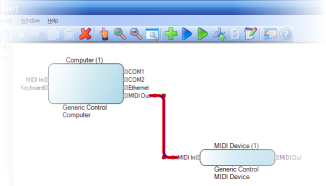
Interconnections are made between Input and Output Ports that either generate or transmit control data. Interconnections between Ports are created by clicking one Port and dragging the mouse onto the other Port: it does not matter which Port you start from. An interconnection line is drawn between the two Ports in the Topology View.
Interconnection Line between two ports
Tip
Interconnections can be moved and routed around by first selecting the Interconnection line by clicking it, then dragging any of the corner handles to the desired location.
In the physical architecture of your system, there may be many I/O ports, routing devices and other components and interconnections between your control computer and the devices being controlled.
However the Topology View represents the logical architecture of your system; it is that deliberately simplified view that represents:
controlling devices with Output ports that generate control data,
controlled devices with Input port that consume control data,
logical connections between the controlling and controlled devices.
Thus, there is no need to show intermediate devices that are not directly controlled by your Stardraw Control program. Examples of devices that might be present in your physical architecture, but are not required in the Topology are:
network routers, switches or hubs,
Wireless Access Points, Internet connections or other network devices,
Power or other non data-related connections.
Note
Similarly, there is usually no need to connect Output Ports which are controllable but do not generate or transmit control data, e.g. video or audio outputs; such ports are the end of the control chain and are themselves being controlled.