Block Schematic Symbol Wizard
When you choose the add or edit a Block Schematic symbol in the User Defined Product Wizard, the Block Schematic Symbol Wizard appears. This wizard allows you to generate Block Schematic symbols quickly and easily, just by entering some values into data fields, rather than drawing the symbol you need.
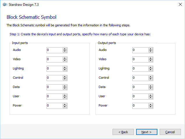
Step 1 - Define IO Ports
 In this first step simply type in, or use the spin controls, to set the quantity of each type of input and output port that you want in your UDP symbol.
The Wizard will create the IO ports on the correct Layers and according to the symbol data specification.
You can assign labels for your IO ports in the next step.
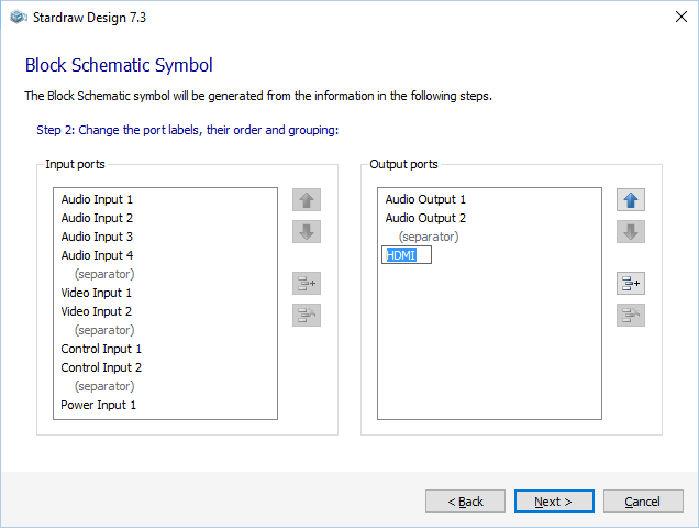
Step 2 - Customize IO Ports
 In this step you can set custom text for IO ports and arrange their layout.
Click on a port label to edit the text that will identify the port.
Use the Up and Down arrows to re-arrange IO ports.
Separators add an extra grid space between IO ports; you can add and remove separators using the  and
and  buttons.
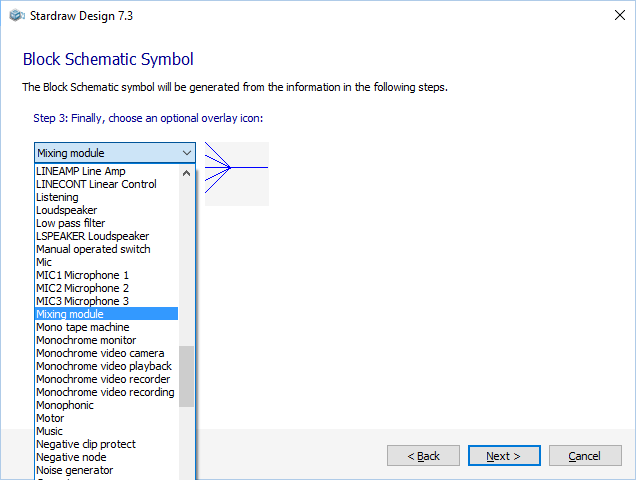
Step 3 - Choose an Icon
 In this optional step you can add an icon to represent the type of product that your UDP represents.
Click on the dropdown to select an icon. A preview of the icon is shown next to the dropdown.
If you wish to add different graphics from other sources to any UDP symbol you can use Symbol Edit mode later.
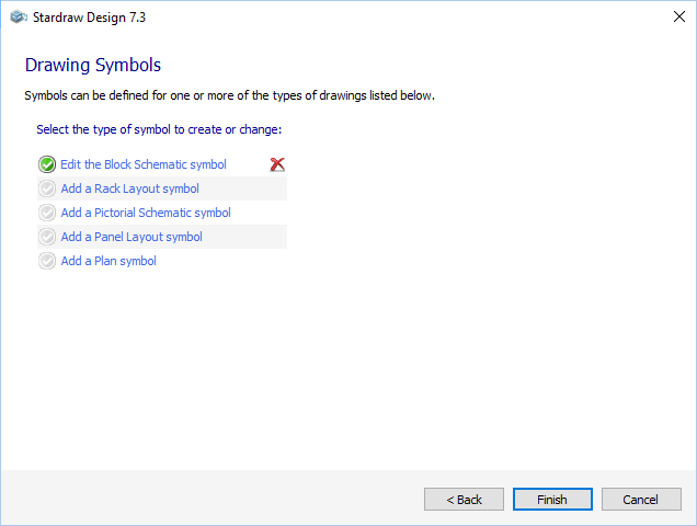
Step 4 - Wizard Complete
 When you have completed the steps in the Block Schematic Symbol Wizard you will return to the symbols page of the UDP Wizard.
The  indicates that a Block Schematic Symbol has been created for the UDP.
If you wish to change the symbol, click on Edit the Block Schematic symbol. This restarts the Block Schematic Symbol Wizard and populates it with the data you have already defined for this symbol. You can use this technique to change the symbol at any time by rightclicking on the UDP in the Product Browser and selecting Edit Product to start the UDP Wizard.
To delete the Block Schematic symbol, click on the  .
.
Click on any of the links to add a new symbol for the UDP, or click on Finish to close the UDP Wizard.
 In this first step simply type in, or use the spin controls, to set the quantity of each type of input and output port that you want in your UDP symbol.
 In this step you can set custom text for IO ports and arrange their layout.
 and
and  buttons.
 In this optional step you can add an icon to represent the type of product that your UDP represents.
 When you have completed the steps in the Block Schematic Symbol Wizard you will return to the symbols page of the
  indicates that a Block Schematic Symbol has been created for the UDP.
 .
.