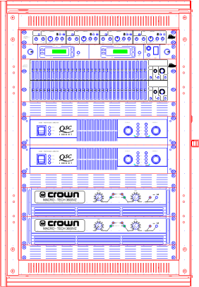


Front View
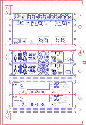
Rear View
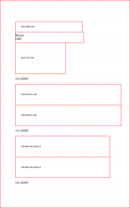
Side View
The Rack Layout module is designed to make it easy to draw highly detailed 19" rack installations. All the symbols provided for this template are drawn to scale with the greatest possible attention to product detail in both front and rear views. A side view is also provided giving outline depth information.
|
|
|
|
|
Front View |
Rear View |
Side View |
The default settings for documents based on the Rack Layout template are as follows:
|
Item |
Default Value |
|
Grid Size X |
25.4 mm (1") |
|
Grid Size Y |
44.45 mm (1.¾", or 1U) |
|
Number of Snaps X |
1 |
|
Number of Snaps Y |
1 |
|
View |
Front View, High Detail |
|
Current Layer |
Front High Detail |
|
Symbol Scale |
1:1 |
The grid in this environment is special in that it is rectangular instead of square. For this environment this makes a lot of sense since horizontal measurements are based on the inch (hence 19" racks) but vertical measurements are based on the U or "Rack Space" which is 1¾".
The symbol shown here is built up using objects on specific layers as described.

Some layers are designed to hold symbol information, some are there so that users can add their own information in the drawings they produce. These layers are indicated by [User].
|
Layer Name |
Purpose/Convention |
Sample |
|
Work Layer |
[User] General purpose working layer. (No objects appear on this layer in symbols) |
|
|
Outline |
The outline of the product. |
|
|
Front Low Detail |
Manufacturer and model number. |
|
|
Front High Detail |
Accurate graphical representation of the front of products (excluding outline). |
|
|
Rear Low Detail |
Manufacturer, model number and outline. |
|
|
Rear High Detail |
Accurate graphical representation of the rear of products (excluding outline). This layer is the only place you will find details of the rear view of products which are not rackmounted. |
|
|
Side View |
Manufacturer, model number and outline showing depth. |
|
|
Clearances |
Not used. Provided for compatibility with legacy applications. |
|
|
Side View Clearance |
Recommended clearances front and back, allowing for connectors, controls and any other elements that may protrude from the overall extents of the product. |
|
|
Guide Lines |
Not used. Provided for compatibility with legacy applications. |
|
|
Module Targets |
Insertion targets for modular equipment which needs to be precisely located within a sub-frame. |
|
|
Titles & Borders |
[User] Drawing border and any information used to reference the drawing (draughtsman, company details, project, drawing number etc.). |
When you drag rack-mountable equipment into your drawing the cursor will be on the bottom left corner of that product.
The insertion point for rack enclosures (found in the Generic Audio library) is at the bottom of the inside left edge, in other words, at the bottom of the left hand rack strip. This is the point which will sit on the grid and allow you to fill the rack with product quickly, easily and properly aligned.
The Rack Layout environment has a front and a rear view. To switch between them use the View buttons on the toolbar. When you go from the front to the rear view the entire drawing will be mirrored, this means that anything you've drawn on a "front facing" layer that's visible will be reversed. If you want to annotate the rear of your rack or add any other objects to the design, be sure to use one of the rear layers (i.e. rear high detail or rear low detail).
|
See Also: |