 Bridges can be used where Cable objects cross each other; the Bridge indicates that one Cable 'jumps over' the other, rather than being connected to it.
 Bridges can be used where Cable objects cross each other; the Bridge indicates that one Cable 'jumps over' the other, rather than being connected to it.
Bridging is a document mode, so when the Bridges button is checked, all horizontal/vertical Cables that cross perpendicularly will include a Bridge automatically, and when it is unchecked all Bridges will be removed automatically.
|
Bridges are created and updated automatically and dynamically as you make changes to your drawing. If you make any changes that impact on a bridged or bridging Cable, any and all Bridges will be redrawn instantly, as soon as the changes are applied.
A Bridge is part of the Cable that it appears in, so the Bridge will be the same color, line style, thickness, and on the same Layer as the Cable of which it is a part.
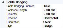
The shape and style of Bridges are defined using parameters in the Document Properties Grid. These parameters apply across the whole document: Bridges are automatic, taking the same settings throughout the document and they cannot be individually modified, added or deleted.
 Cable Bridging Enabled: True = On, False = Off. This value mirrors the state of the Bridges button in the toolbar and defines whether Bridges are On or Off.
Coalesce Length: defines the distance between Bridges at and below which adjacent Bridges will be joined to create one, large bridge. If you do not want Bridges to join up with each other ('coalesce') set the value to 0. The default value is 2.5mm, corresponding to the default distance between gridpoints in Block Schematic and Pictorial Schematic drawings.
Diameter: defines the diameter of the circle that the Bridge is based on. The default value is 2.5mm, corresponding to the default distance between gridpoints in Block Schematic and Pictorial Schematic drawings.
Direction: with values of Horizontal and Vertical, use this property to choose whether Bridges are inserted into the Horizontal or Vertical segments of crossing Cables. Default value is Horizontal.
Orientation: with values of Over and Under, use this property to choose the orientation of Bridges. Default value is Over.
Style: use Style to define the appearance of the Bridge. 'Bridge' creates a semi-circular 'hump-backed' bridge and 'Gap' creates a small break in the crossing cable. Default value is Bridge.