 security
system is an automated digital public address and emergency evacuation
system, and uses a TCP/IP based protocol for sophisticated bidirectional
control and communication.
security
system is an automated digital public address and emergency evacuation
system, and uses a TCP/IP based protocol for sophisticated bidirectional
control and communication.|
How Do I ... ? |
Bosch Praesideo |
|
|
The Bosch Praesideo security
system is an automated digital public address and emergency evacuation
system, and uses a TCP/IP based protocol for sophisticated bidirectional
control and communication.
There is a multimedia walk-through of these techniques in the online
Technical
Resources.
A Praesideo system is generally comprised of a Network Controller and one or more audio power amplifiers, audio distribution devices, microphone call stations and PA speakers.
The Praesideo system can be configured using the Network Controller's built-in web interface. With this, you can configure the numbers of audio inputs and outputs, how your external hardware, amplifiers, background music sources, etc. are connected, and the audio zones that correspond to your building or installation environment.
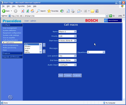
The Praesideo Network Controller web interface
You can also create Call Macros using the web interface, which are preset announcements with several configurable properties:
Priority: specifies the call's importance: a higher priority call will override a lower priority one if more than one call is being played simultaneously.
Start Tone: an audio chime sample played at the beginning of the announcement.
Messages: a list of prerecorded messages to play, such as an intro, the announcement, warning or emergency message, and a thank-you.
Repetitions: the number of times the messages are played.
Live Speech: specifies whether a live announcement can be inserted as part of the call.
Audio Input: the audio input of the Live Speech microphone.
End Tone: an audio chime sample played at the end of the announcement.
Once configured, Call Macros can then be triggered automatically by the security system, or other monitored event, or manually by an operator using a microphone call station or panic button. The Network Controller can also route the announcement to any zone or group of zones.
The TCP/IP protocol provided by the Praesideo enables an external system, such as Stardraw Control, to create and play announcements on-the-fly. This means that instead of having to preconfigure all the calls using the Network Controller's web interface, Stardraw Control can be used to easily generate any call or announcement preset at run-time.
To control a Praesideo system you need to add a Network Controller device driver to your topology:
In the Topology View,
locate the LBB4401-00 Network Controller
device in the Bosch Security Systems
category of the Stardraw Control Products List:
Click and drag the device to add it to your topology.
Add a connection from your Computer's Ethernet port to the IP port of the new device.
In the Property Grid
is the Network Controller's IP configuration properties:
IP Address: set this to your Network Controller's IP Address;
the default value is 192.168.100.101
IP Port: 9401
IP Password: set this to your Network Controller's login password;
the default value is admin
IP UserName: set this to your Network Controller's login username;
the default value is admin
When the compiled executable is running, the driver uses the IP configuration above to log into the Network Controller. Once successfully logged in, the Network Controller and driver exchange heartbeat messages every 15 seconds.
This enables the Network Controller to monitor control applications that are connected to it, and for them to monitor the Network Controller. If the communication link is broken, either end can detect the absence of heartbeat messages, and react accordingly.
This is a powerful feature of many bidirectional protocols: each end of the communication link is aware of the other, and can respond with status changes, success or failure of commands, and other alerts or errors.
A call or announcement can be generated on-the-fly by your control program, using the same set of properties as the Network Controller's web interface.
In the Forms View, from the Windows tab of the Toolbox, click and drag a Button control onto the form.
In the Property Grid set the button's Text property to "Start Call".
Double-click the button
to display the Actions Editor.
Note that the selected event is button1.Click:
this is the event that we wish to capture to generate a call.
Add the following Actions to configure the call properties of the LBB4401-00 (1) device:
|
Property |
Value |
|
Priority |
50 |
|
LiveSpeech |
False |
|
Partial |
False |
|
Routing |
"All" |
|
StartChime |
"3-tone chime A" |
|
Messages |
"attu,closeu,tyu" |
|
Repeat |
0 |
|
EndChime |
"3-tone chime B" |
Finally, add the following
Action to start the call:
Devices –
LBB4401-00 (1) –
Ip –
StartCall
Click Ok to close the Actions dialog.
Run the form and click Start Call: the Actions you configured will generate and start a call at priority 50 which begins with the "3-tone chime A" chime, plays the "attention", "closing" and "thank-you" messages once only, and ends with the "3-tone chime B" chime. No live speech is inserted, and the call is played to all zones.
You could set up several 'call' buttons using this approach, each of which configures and plays a particular type of announcement.
Tip
You could also provide a more flexible solution to the operator, and allow them to select the messages from a drop-down list, or change the zone, or start and end chimes as they wish. The call properties listed above could then be set from the operator's selection, rather than from hardcoded values.
The Network Controller device driver also generates a number of events. These can be used to notify the operator of changes in status, and to keep your User Interface in sync with the Network Controller's current configuration.
Some are property change events which are fired whenever a property value is changed, e.g.:
OnAudioInputChanged,
OnMessagesChanged,
OnPriorityChanged
There are call progress events that indicate the real-time status of a call, such as:
OnCallStateStart,
OnCallStateMessages,
OnCallStateEnd
Finally there are system status events like:
OnHeartBeat,
OnProtocolError,
OnConnectionLost