The following layers are created by default in this environment and the symbol shown here is built up using objects on specific layers as described.
Some layers are designed to hold symbol information, some are there so that users can add their own information in the drawings they produce. These layers are indicated by [User].
|
Layer Name |
Purpose/Convention |
Sample |
|
Work Layer |
[User] General purpose working layer. (No objects appear on this layer in symbols) |
|
|
Outline |
The outline of the product. |
|
|
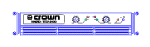
Front Low Detail |
Manufacturer and model number. |
|
|
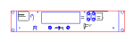
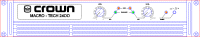
Front High Detail |
Accurate graphical representation of the front of products (excluding outline). |
|
|
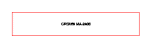
Rear Low Detail |
Manufacturer, model number and outline. |
|
|
Rear High Detail |
Accurate graphical representation of the rear of products (excluding outline). This layer is the only place you will find details of the rear view of products which are not rackmounted. |
|
|
Side View |
Manufacturer, model number and outline showing depth. |
|
|
Clearances |
Not used. Provided for compatibility with releases of ShuttleCAD earlier than version 4. |
|
|
Side View Clearance |
Recommended clearances front and back, allowing for connectors, controls and any other elements that may protrude from the overall extents of the product. |
|
|
Guide Lines |
Not used. Provided for compatibility with releases of ShuttleCAD earlier than version 4. |
|
|
Module Targets |
Insertion targets for modular equipment which needs to be precisely located within a sub-frame. |
|
|
Titles & Borders |
[User] Drawing border and any information used to reference the drawing (draughtsman, company details, project, drawing number etc.). |
|